English
 русский
 عربى
عربىElectrical infrastructure decisions increasingly depend on how integrated and space-efficient a system can be while maintaining reliability. A compact transformer substation is frequently discussed alongside a unit substation transformer solution, especially in industrial and commercial distribution projects where system configuration and internal components directly impact performance and maintenance strategies.
A unit substation transformer system is not a single enclosed box but a coordinated assembly of multiple electrical sections. These sections are engineered to work together as one functional unit, enabling voltage transformation and power distribution tailored to specific load requirements.
Core Structure of a Unit Substation
A unit substation typically consists of three primary sections that are electrically and mechanically connected:
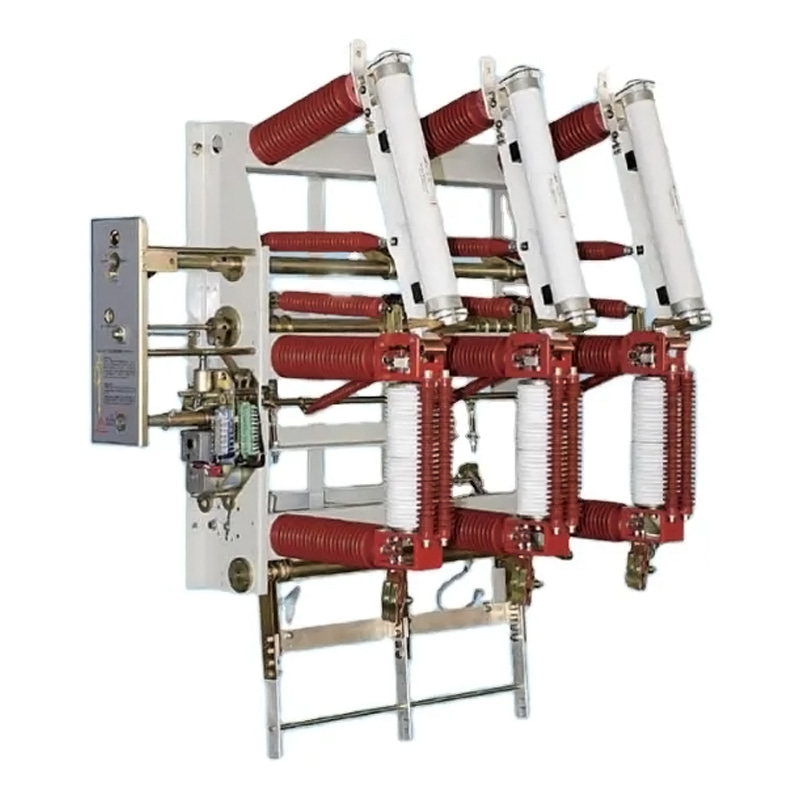
1. Primary (Medium-Voltage) Section
This section receives incoming power from the utility grid.
Typical components include:
Medium-voltage switchgear
Load break switches or circuit breakers
Protection relays and metering devices
Surge arresters and disconnect switches
Voltage ranges often fall between 6.9 kV and 69 kV, depending on system design
Purpose:
Control incoming power
Provide isolation and fault protection
Ensure safe switching operations
2. Power Transformer Section
At the center of the system sits the transformer, the more critical and largest component.
Key functions:
Step down voltage from medium voltage to usable low voltage
Match plant or facility load requirements
Common technical parameters:
Capacity: 100 kVA up to several MVA
Cooling types:
Oil-immersed (ONAN / ONAF)
Dry-type (cast resin)
Typical secondary voltage: 400V / 480V / 690V
The transformer defines the overall rating and influences the physical layout of the entire unit substation.
3. Secondary (Low-Voltage) Distribution Section
This section distributes power to end-use equipment.
Components include:
Low-voltage switchboards
Circuit breakers (ACB/MCCB)
Busbars and distribution feeders
Power monitoring systems
Purpose:
Deliver electricity safely to loads
Enable load management and protection
Support automation and monitoring
Structural Integration vs Compact Design
Unlike a compact transformer substation, which integrates all components into a sealed enclosure, a unit substation transformer configuration is often:
Installed indoors or in electrical rooms
Arranged in line or L-shaped layouts
Accessible for maintenance from multiple sides
This structural difference leads to:
Greater flexibility in configuration
Easier component replacement
Larger installation footprint
By contrast, compact substations emphasize enclosure-based integration and reduced space requirements, combining all functions into a single housing
Auxiliary and Protection Systems
Modern unit substations include more than just the three main sections. Additional subsystems enhance safety and operational stability.
Protection Systems
Overcurrent protection
Short-circuit protection
Earth fault detection
Monitoring Systems
Digital meters
SCADA communication interfaces
Temperature and load monitoring
Control Components
Relay panels
Control wiring
Automation modules
These systems ensure that the substation operates safely under varying load conditions and responds quickly to faults.
Internal Layout Configurations
Several layout options are commonly used depending on available space and operational requirements:
Linear Arrangement
MV → Transformer → LV in a straight line
Suitable for narrow rooms
Back-to-Back Layout
Transformer centered between MV and LV
Reduces cable length
Segregated Rooms
Each section installed in separate compartments
Used in high-capacity industrial plants
Compared with compact substations that follow predefined enclosure layouts, unit substations offer more customization.
Material and Build Considerations
Component arrangement is closely tied to material selection and construction methods:
Steel-framed switchgear enclosures
Copper or aluminum busbars
Fire-resistant insulation materials
Ventilation systems for heat dissipation
Durability and safety standards often follow IEC and ANSI guidelines to ensure long-term operation.
Application Scenarios
Unit substations are widely used in:
Manufacturing plants
Data centers
Oil & gas facilities
Large commercial buildings
Their flexibility makes them suitable for projects requiring:
Custom voltage levels
High load capacity
Expandable distribution systems
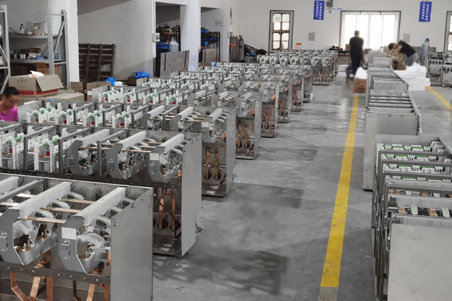
Manufacturer Perspective
Engineering teams focus on balancing modularity and reliability. Qinghang Electric Co., Ltd., for example, develops unit substation transformer systems with configurable switchgear and transformer combinations, allowing adaptation to varying industrial load profiles.
Design improvements often include:
Compact busbar routing
Integrated protection relays
Pre-tested assemblies for faster installation
Key Takeaways
A unit substation is more than a transformer—it is a coordinated system made up of:
Medium-voltage input control
Voltage transformation
Low-voltage distribution
Compared with a compact transformer substation, it provides:
Greater design flexibility
Easier maintenance access
Broader customization options
Understanding these internal components helps project planners make informed decisions about system architecture, especially when balancing space, performance, and long-term operational needs.