English
 русский
 عربى
عربىUrban expansion, industrial upgrades, and distributed energy projects continue to reshape how electrical infrastructure is deployed. Questions about footprint and installation flexibility are becoming more frequent across engineering forums and procurement discussions. A compact transformer substation is often evaluated alongside a unit substation transformer solution, especially in projects where land use, accessibility, and construction timelines must be carefully balanced.
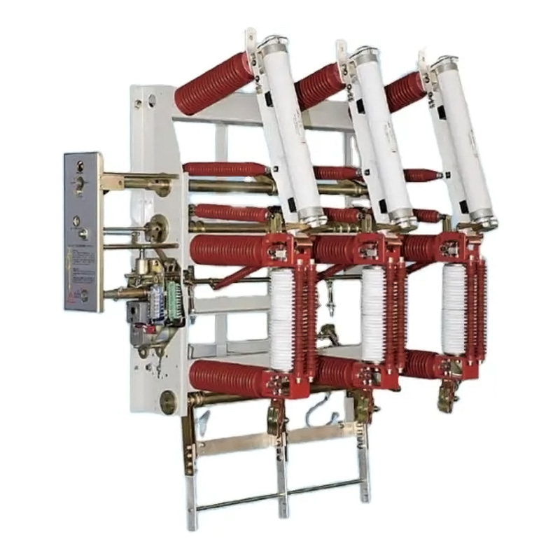
Compact transformer substations are designed as factory-assembled systems integrating medium-voltage switchgear, transformers, and low-voltage distribution equipment within a single enclosure. This integrated structure significantly reduces the required installation footprint compared with conventional substations.
Footprint Dimensions and Typical Layout
A compact substation is not a one-size product. Physical dimensions vary depending on voltage level, transformer capacity, and configuration.
Typical ranges observed in industry specifications include:
Rated power: 50 kVA to 5000 kVA
Primary voltage: 10 kV / 20 kV / 33 kV
Typical footprint: approximately 2.5m × 2.5m up to 3.5m × 6m
This means a complete power distribution unit can often be installed within a footprint similar to a small equipment room or parking space. Compared to traditional substations that require separate transformer yards, switchgear rooms, and cable trenches, this represents a substantial reduction in land use.
Key layout characteristics:
Fully enclosed steel or concrete housing
Segregated compartments for MV, transformer, and LV sections
Cable entry from bottom or side depending on site conditions
Optional walk-in or non-walk-in design
Such compactness explains why these substations are widely used in urban infrastructure, construction sites, and renewable energy installations where space is constrained .
Space Beyond the Equipment Itself
The equipment footprint alone does not define total space requirements. Practical installation requires additional clearance zones for safety, ventilation, and maintenance.
1. Safety Clearance
Adequate spacing must be maintained around the enclosure to allow:
Door opening and safe operator access
Emergency isolation and inspection
Compliance with electrical safety standards
2. Ventilation and Heat Dissipation
Transformers generate heat during operation. Even with natural air cooling (ONAN), airflow paths must remain unobstructed.
Common recommendations include:
Avoid placing substations in low-lying or enclosed areas
Maintain open space around ventilation panels
Prevent obstruction of transformer room doors
3. Cable Routing Area
Cable trenches or ducts require planning:
Incoming medium-voltage cables
Outgoing low-voltage feeders
Grounding grid connections
4. Foundation and Elevation
A raised concrete base is typically required to:
Prevent water ingress
Support equipment weight (up to 20,000 kg in some cases)
Comparison With Unit Substation Transformer Layout
A unit substation transformer system follows a different spatial philosophy. It consists of separate but closely coupled sections:
Primary switchgear
Transformer
Secondary distribution equipment
While these components are integrated electrically, they are not always enclosed in a single compact housing. As a result:
Indoor installations may require dedicated electrical rooms
Outdoor setups may need fenced areas
Layout flexibility increases, but footprint typically expands
Compact substations prioritize space efficiency and modular deployment, whereas unit substations prioritize customization and system scalability.
Application-Driven Space Considerations
Space requirements vary significantly depending on application scenarios:
Urban Distribution Networks
Limited land availability
Preference for compact transformer substation designs
Often installed near buildings or roadside
Industrial Facilities
More flexible layout options
Unit substation transformer solutions may be preferred for higher customization
Space allocated within electrical rooms or substations
Renewable Energy Projects
Compact footprint reduces civil engineering costs
Containerized or skid-mounted substations are common
Engineering Factors That Influence Size
Several technical parameters directly impact substation dimensions:
Transformer capacity (kVA rating)
Voltage level (e.g., 11kV vs 33kV)
Cooling method (oil-immersed vs dry-type)
Protection system complexity
Enclosure material (steel, concrete, or composite)
Higher-capacity systems naturally require larger enclosures, especially when additional protection or automation components are integrated.
Manufacturer Perspective on Space Optimization
Manufacturers are continuously improving internal layouts to reduce footprint while maintaining safety and performance. Qinghang Electric Co., Ltd., for example, focuses on modular compartment design and optimized cable routing to support flexible installation in constrained environments.
Design improvements typically include:
Compact switchgear arrangements
Integrated protection and monitoring systems
Pre-installed wiring to reduce on-site work
These approaches help reduce not only physical space requirements but also installation time and labor costs.
Practical Takeaways
Understanding space requirements goes beyond measuring equipment dimensions. A realistic evaluation should consider:
Equipment footprint
Safety and maintenance clearance
Environmental conditions
Cable routing and foundation design
A compact transformer substation can significantly reduce land usage and simplify deployment, while a unit substation transformer configuration offers more flexibility at the cost of larger spatial requirements.
Projects with strict land constraints tend to favor compact solutions, whereas facilities requiring tailored electrical systems may allocate additional space for unit substations.